Tuesday, December 13, 2016

Hot off the Press!!!


The Bakers at Sweet Tooth have finally unlocked the perfect recipe for our Cupcake Yo-yo. Take a closer look at our process here .

Our Cupcake Yo-Yo was composed of 4 unique parts, two injection molded parts and two thermoformed parts. Each Yo-Yo is symmetric, with a cake, frosting and sprinkles on both sides. It also comes with a stand in the shape of a cupcake cup to place the Yo-Yo when not in use.
Capture.PNG
Exploded View of Cupcake Yo-Yo

The most challenging part to make was the injection molded frosting. Due to its complex geometry the part was made using the CNC lathe and 3D mill machining. The core mold was composed of shutoff surfaces ( is this what they are called?) such that holes for the sprinkles could be made while the cavity mold took the shape of the swirl for the frosting. The bottom of the frosting consisted of some notches so that we can have sprinkles on the bottom layer while the rest of the bottom had a straight wall to allow us to press-fit the frosting with the base of the Yo-Yo

.
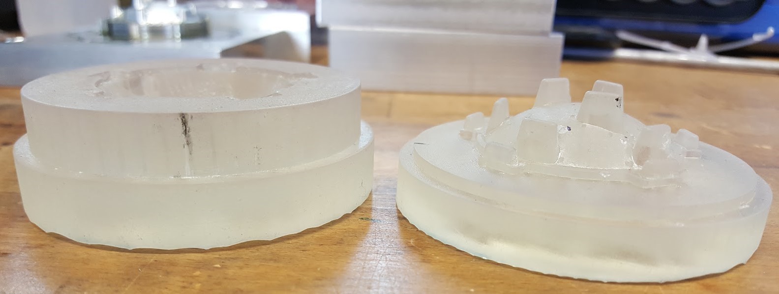
Frosting Core and Cavity Mold


Finished frosting top and bottom  

The base of the Yo-Yo was an injection molded cake. The first iteration of this mold consisted of notches matching those in the frosting so that the two pieces would be a perfect press fit with the sprinkles sandwiched in between. However initial testing of the part showed us that we would need very tight tolerances so that the frosting and cake press-fit together perfectly. Therefore we re-machined the mold to remove the notches and only have an outer straight walled diameter to engage with the frosting.


Finished Cake

In between the frosting and cake is the thermoformed sprinkles that poke through the holes made in the frosting. We decided to use SLA printing to make the thermoform molds since we had tight features that would be difficult to machine. We first tried using a female mold for vacuum forming. However the the vacuum holes couldn't draw the plastic far enough into the small holes to give them enough height to poke through the injection molded frosting. Next we made an SLA printed male mold for drape forming which produced sprinkles with the desired height but also introduced webbing in the part which would interfere with the frosting. Finally we used both the male and female mold to produce the desired results; with the male mold sitting on the bottom to allow for drape forming, and then the female mold aligned perfectly to make sure the top and bottom molds met enough to mold the plastic into the proper shape but not too much as to break the molds or the thermoformed part.


Sprinkles Male and Female Mold


Finished Sprinkles Part

Finally, we made a thermoformed cup to properly display the Yo-Yo. This part was unique from other thermoformed parts usually made in 2.008 because it was very tall, which means that the plastic had to be drawn in significantly from the sides in order to form to the mold. In order to make this part we had to use new thermoforming routines such as plug assist to seal the plastic to the bottom of the mold so the vacuum holes could effectively draw in the plastic to the shape of the mold.


Plug Assist Process

Through this process we were able to achieve a very realistic cup shape.


Final Cup

Overall our bakers were satisfied with the end result. We succeeded in unlocking the recipe for a fully functional and realistic cupcake Yo-Yo.

DSC08030 (Kevin Leonardo's conflicted copy 2016-12-11).JPG

We owe part of our success to the testing stages early on in which we used FDM to visualize our parts quickly and decide on any changes that needed to be made.

By 3D printing the cup we determined the largest size cup we can have to fit inside the tooling. It also helped us realize that the cup is unlikely to buckle outwards as was our fear. For the rest of the 3D printed parts we were able to visualize the scale of our Yo-Yo. We decided to increase the size of our parts to better fit in the hand and be comparable to a standard Yo-Yo size.

Design and Measure Specifications

Here are tables comparing our design specifications to measured specifications:


Design Specification
Measured Specification
Cake press fit outer diameter
1.637” ± 0.0025”
1.638”±  0.001”
Frosting press fit inner diameter
1.627” ± 0.0025”
1.622” ± 0.001”
Cup height
1.375” ± 0.75”
1.368” ± 0.016
Sprinkles size
0.387” ± 0.0025”
0.388” ± 0.003”


Modified Specification for Mass Production
Cake press fit OD
1.637 ± 0.0025”
Frosting press fit ID
1.625 ± 0.0025”
Cup height
1.370” ± 0.75”
Sprinkles diameter
0.387” ± 0.0025”

Cake : The cake is within the specifications. This means that we properly accounted for shrinkage while making the molds. Therefore for the modified specifications the same average can be used with a tolerance of .0025” for the press fit.
Frosting : The frosting is within specifications, but just barely. The average measured diameter is not exactly the measurement from the intended design. This can be due to the fact that it was difficult to measure the diameter of the press fit due to the notches. It is likely that the measured length is not exactly the diameter of the part, meaning the measured average diameter should be bigger and potentially within the specifications. In order to maintain a good press fit with the cake a modified specification of 1.625” ± 0.0025” should be used, to maintain close to a 0.01” press fit and be within the range of our produced parts.

Cup: The cup is well within the specification. This is because the tolerance for the part was very wide.

Sprinkles : The sprinkles are within the specifications, meaning the process parameters for thermoforming were chosen such that the plastic conformed to the mold very well. The modified tolerances we need are very small since the sprinkles have to fit well into the holes made in the frosting.

Cost Analysis

1.jpg
    We received our quotes a for mold tooling costs and SLA printed parts from ProtoLabs. Also we made assumptions of the cost of machines by searching the internet. We used the equations given in the lecture slides to calculate the total unit costs.

2.jpg

3.jpg


$/unit
2.008: 50 units
Additive Manufacturing: 50 units
Large-Scale: 100,000 units
Material Cost
30.6812
0
30.5042
Equipment Cost
24.5000
0
0.0358
Tooling Cost
23.2384
0
0.1162
Overhead Cost
43.2000
46.4500
0.0093
Other Cost
0
235.300
0
Total Cost
121.6196
281.7500
30.6655

For prototyping additive manufacturing would be the best way to go because of the lower unit cost as well as the shorter production time. As we begin increasing the production volume, however, the price of AM begins to approach the mid-$200, whereas 2.008 methods approach about $70. For larger volumes, the 3D printer begin to be unable to meet up with the increasing demands and prices for the resin also increase the costs.

Design Changes for mass production


One of the main constraints from the 2.008 manufacturing equipment is how many parts we are able to produce at one time. With our the injection molding and thermoforming machines at our disposal, we were restricted to making one part at a time, whereas mass production would allow us to reach a target goal faster. Through the use of more machines and producing more parts per cycle, we would increase our production rate significantly. Also lab hours were one of our biggest constraints. Without the 8 AM - 5 PM limit, we would be able to produce parts overnight if need be with the large scale manufacturing equipment.
To meet the constraints of 2.008 manufacturing equipment, the biggest adjustment that we had to make was the diameter of our cup because the mold holder for the thermoforming machine had a diameter of 2.74 inches and we had initially designed it to be bigger. At the end, it came out nicely so I don't think we would change the dimensions for mass production. 

Wednesday, November 30, 2016

Optimization of Cupcake Recipe

The Bakers at Sweet Tooth are getting very close to unlocking the recipe for the perfect Yo-Yo. In this post we would like to share a closer look into our parts including our most interesting injection molded part; the frosting.   

Frosting

The frosting was the most difficult part of our cupcake to perfect. After several bumps on the road we were finally able to achieve a finished part.  

Mold Design

We began by modeling the frosting in SOLIDWORKS with all the specifications that we need.

Using the SOLIDWORKS mold making function we generated models of our molds.

cupcake_yoyo_frosting_plain_v4-Cavity.JPG cupcake_yoyo_frosting_plain_v4-Core.JPG
Mold Cavity Mold Core

Manufacturing Process

The cavity mold for the frosting was made mostly on the CNC lathe, the mill was only used to make the runner to allow the plastic to flow into the mold. For the core mold however, due to the complexity of its shape, we first machined the general shape on the CNC lathe and then used the 3D mill to cut out the more detailed features.


Machined core and cavity molds

We were able to machine these molds using the following process plan:

Frosting Cavity Process Plan:

Step
Operation
Machine
Tool
Justification
1
Rough bore
Daewoo Puma Lathe
10
For the first two layers of the frosting we want to remove as much material as the size of the tool allows
2
Finish cut
Daewoo Puma Lathe
10
Get a good surface finish for the first two layers
3
Rough bore
Daewoo Puma Lathe
5
For the 3rd layer of frosting because tool 10 is too big to reach this part of the mold
4
Finish cut
Daewoo Puma Lathe
5
Get a good surface finish for the 3rd layer
5
Groove
Daewoo Puma Lathe
9
To be able to get the tip exactly or close to the way we designed it, we made a groove to prepare the finish cut of the tip
6
Finish trepan
Daewoo Puma Lathe
7
We wanted a tool small enough to get inside the tip and finish it
7
Contour
Prototrack Mill
9
Make the runner
8
Ream
Drill press
.126 reamer
Open up the ejector pin holes

Frosting Core Process Plan:

In order to make the 3D machining of the core mold easier for the tools, we outlined the rough shape of the part first on the lathe, then we 3D machined it

Step
Operation
Machine
Tool
Justification
1
Rough cut
Daewoo Puma Lathe
1
Roughly carve out the shape of the mold
2
Finish cut
Daewoo Puma Lathe
13
Get a good surface finish before the 3D machining
3
Surface parallel
Hass mill
9
Make the dome shape of the mold
4
Surface Radial (x7)
Hass mill
9
Contour the 7 posts on the dome for the sprinkles holes on the frosting
5
Pocket facing
Hass mill
15
Machine the plane around the bottom of the dome and contour the 5 small posts sitting on the edges
6
Pocket remachining
Hass mill
20 (1/16” 5 degrees tapered end mill)
Contour the posts that were very close to the dome
7
2D contour
Hass mill
7
Rough cut of the edges of the frosting
8
2D contour
Hass mill
6
Better finish of the edges of the frosting core
9
2D contour
Hass mill
19(extended ⅛” ball endmill)
Even better finish of the edges of the frosting core and make sure we get the fillets that we added
10
Center drill
Prototrak mill
⅛” ball end mill
Mark the ejector pin holes
11
Drill
Prototrak mill
17
Drill out the ejector pin holes
12
Ream
Drill press
.126 reamer
Open up the ejector pin holes

We made the mistake of not drilling the ejector pin holes before giving the dome shape to the core mold and it was very difficult to do it after. The drill bit that we use (tool #17) was wandering off the holes and broke in the hole at the tip. As result we had to plug the hole in order for plastic not to get in it.


Core mold with plugged hole in the center

Injection Molding Process Parameters

Injection Hold

Injection Hold Pressure Profile P7-P16
300
400
500
600
650
700
700
700
700
700
Injection Hold Time
Z2=8
Cooling Time
Z4=25
Set Screw Feed Stroke (Shot Size)
C1=1.5

Injection Boost

Injection Speed Profile: V12-V21
3
3
3
3
3
2
1
.4
.2
.1
Injection Boost Pressure
P6=1600

Screw Feeding

Screw Feed Delay Time
Z3=10

Ejector

Ejector Counter
AZ=2

⅛” Ejector Pin Length: 5.446”  (Quantity: 4 )
Total Shim Thickness: 0.094”
¼” Ejector Pin Number: 2
Special Ejector Pin Length: 5.849”, 5.812”, 5.811”, 5.819”

We began with a shot size of 1.7 and an uniform injection pressure of 700. However these parameters resulted in a significant amount of flash, so we reduced the shot size to 1.5. We also realized that the parts were coming out very hot, so we increased the cooling time to 25 seconds to allow the part to cool more in the mold and reduce shrinkage and warpage. At this point we were still getting some flash but the machine would inject to zero within the first stroke. We also noticed that the the screw would bounce back slightly in the first stoke. This hinted to us that the beginning injection hold pressure was too large. Lowering the injection hold pressure at the start lowered the force of the plastic being pushed into the machine. This also decreased the flash slightly. To get rid of the flash completely we also decreased the end values for the injection speed profile. This pushes the plastic into the mold slower, meaning the plastic is more viscous going into the mold, reducing flash. With this parameter changed we were able to eliminate the flash completely.

We also noticed that we have some voids in the bottom of the frosting. We tried to increase the shot size to fill the voids with plastic, and the injection pressure to pack the plastic into the voids. However, these changes did not remove the voids and started to introduce flash to our part again. We decided that we would keep the parameters that produced a part with no flash, and produce the frosting in a darker color so that the voids would not be visible unless you cut it open.  

frosting void.jpg 20161206_141621.jpg

Frosting with voids Frosting without visible void but with little flash

It took us 3 minutes and 45 seconds to produce 5 parts, therefore it will take us 75 minutes to produce the 100 parts that we need for out Yo-Yos.

Cake

Through optimization of the injection molded cake we learned about the importance of tolerances, and how design for manufacturing greatly influences the finish of a part.

Our original mold design included a ring to press fit with the frosting, and notches that held the sprinkles and frosting together on top of the cake. However,that the notches in the mold were too thick and produced parts that were significantly warped due to uneven cooling time.We tried to increase the injection pressure and modify the injection speed pressure to decrease the warpage but that introduced too much flash to our part and resulted in burn marks. We soon realized that we would not be able to eliminate the warpage without having flash, so instead we modified the mold to include dowel pins in the notches in order to maintain a uniform wall thickness and a more even cooling time.

20161202_111828.jpg 20161202_111303.jpg

Warped due to uneven cooling time Modified original core mold with pins

At this stage we were also able to produce our first frosting part. Unfortunately the frosting and cake did not fit together; the press fit on the cake was too big to fit inside the frosting. Since the frosting mold was more complex than the cake mold we decided to remake the cake mold to achieve the press fit. For the new cake mold we removed the notches since we did not necessarily need them to make the press fit. Instead we used a simple ring to engage with the frosting and hold all the pieces together.


New core mold without notches

For the optimization process of the new mold we began with a shot size of 1.7 which gave us short shot, so we increased shot size until we filled the mold completely. With a shot size of 2 we were filling the mold but still resulting in some flash so we changed the injection speed profile to be slower at the end. This injects the plastic into the mold slowly at the end which increases the viscosity which reduces flash. With these parameter changes we were able to remove the flash. We also tried increasing the cooling time to 45 seconds to see if that reduces the shrinkage to improve the press fit, but we found that the diameter of the part did not change. Therefore we kept the cooling time at 30 seconds to reduce our production time.

At the beginning we were also producing parts with burn marks, which means that there was trapped air in the mold that was combusting. To solve this problem we drilled a .03" hole in the part of the mold where the air was trapped to allow it to escape. This got rid of the burn mark and produced perfect parts.  

After testing and optimizing the frosting and the cake, some key design for manufacturing considerations that we should have made are:
  1. Make sure the critical dimensions of our part have the right tolerances in order to adjust our parts easily if they don’t fit in the case of a press fit
  2. Make sure our design allows us to measure the critical dimensions of our parts because it was difficult to measure the inner diameter of the frosting
  3. Underestimate the diameter of the part that fits inside the other in a press fit situation (the cake in this case), because we can modify the mold of the part instead of remaking it

Cup

To make the sprinkles and the cup using thermoforming, our team and the Daves pushed the bounds of the thermoforming processes that are used for 2.008.  

With the help of new thermoforming routines such as the plug assist, we were able to achieve drastically better drape forming than we had been able to prior (watch a video of the process here):


The plug assist sealed the plastic to the bottom of the mold so the vacuum holes could effectively draw in the plastic to the shape of the mold, and we got the distinctive cupcake cup shape we were looking for.

Sprinkles

New-to-2.008 thermoforming techniques also helped us improve the shape of the sprinkles.  The sprinkles are designed to fit in between the cake base and the frosting (and stick up through the frosting), so it's key that the sprinkles are both tall enough to poke through the frosting and match the inner shape of the frosting well.

In our first iteration of sprinkles thermoforming, we 3D printed via SLA a female mold that would vacuum form the sprinkles by drawing plastic down into the cavities
IMG_9482.JPG
Female mold

The sprinkles we made using this method were not up to the standards of our bakers.


The sprinkles we produced with this mold were very small/short - the vacuum holes couldn't draw the plastic far enough into the small holes to give them enough height to poke through the injection molded frosting.

Next, we tried using a male SLA printed mold for drape forming of the sprinkles:


Male mold
Photo%2BNov%2B23%252C%2B11%2B48%2B53%2BAM.jpg

Sprinkles with web between them

From the drape forming, we got sprinkles that had the required height, but didn't conform well to the inside of the frosting mold.  This was because of the webs (the folds of plastic) that formed between some of the sprinkles that were closer together.  No amount of parameter changes would reduce these webs enough to meet our specifications, so we decided to use both the male and female molds together to create the shape we were looking for:


Female and male molds


For this process, precision was key.  The two molds needed to be very well aligned with respect to each other in order to avoid parts crashing and putting undue wear on the molds.  The platen height was also set carefully to make sure the top and bottom molds met enough to mold the plastic but not too much as to break the molds or the thermoformed part.   After aligning the molds correctly, we found a sequence of steps and parameters that entirely eliminated the webbing between sprinkles.  We increased our heating time to increase the malleability of the plastic and made sure the two molds came together before the bottom vacuum came on. With these changes we were able to make the part almost exactly to our specifications!

The lesson that we learned here was to not design features that are too close to each other because of the constraints that thermoforming imposes. Moreover, as stated earlier, the sprinkles had to fit into the frosting, as a result, the holes on the frosting had to exactly match the placement of the sprinkles. This caused a problem while machining the core mold of the frosting, because the tools of the milling machine are not long enough and small enough to precisely go in between those features without reducing the surface quality.